Open Access is an initiative that aims to make scientific research freely available to all. To date our community has made over 100 million downloads. It’s based on principles of collaboration, unobstructed discovery, and, most importantly, scientific progression. As PhD students, we found it difficult to access the research we needed, so we decided to create a new Open Access publisher that levels the playing field for scientists across the world. How? By making research easy to access, and puts the academic needs of the researchers before the business interests of publishers.
We are a community of more than 103,000 authors and editors from 3,291 institutions spanning 160 countries, including Nobel Prize winners and some of the world’s most-cited researchers. Publishing on IntechOpen allows authors to earn citations and find new collaborators, meaning more people see your work not only from your own field of study, but from other related fields too.
Like many other textile industries, batik requires a lot of water, and its use of different dyes and other chemicals accounts for most of the water pollution (17–20%). It can reduce light penetration, which in turn may decrease photosynthetic activity, and it may also have an impact on the quantity of oxygen available for the biodegradation of aquatic microbes. Many dyes, including diazo (-N〓N-), direct, and basic dyes, are challenging to work with using standard techniques, and the byproducts may occasionally be quite hazardous. Photocatalysis with various semiconductor materials has been the focus of investigations in recent years for the wastewater treatment application. Among many semiconductors, because of its strong photocatalytic activity, outstanding stability, lack of toxicity, and affordability, TiO2 is still the most extensively used photocatalyst. When a catalyst (TiO2) is exposed to ultraviolet (UV) light, hydroxyl radicals (•OH) are produced in the UV/TiO2 photocatalytic oxidation process. Organic materials therefore mineralize into CO2, H2O, and inorganic components. In this chapter the application of continuous tubular photoreactor with TiO2 nanoparticles as a catalyst for Batik wastewater treatment is reviewed.
Faculty of Engineering, Department of Chemical Engineering, Universitas Diponegoro, Semarang, Indonesia
Dina Lesdantina
Faculty of Engineering, Department of Chemical Engineering, Universitas Diponegoro, Semarang, Indonesia
Ariana Aisa
Faculty of Engineering, Department of Chemical Engineering, Universitas Diponegoro, Semarang, Indonesia
Farida Diyah Hapsari
Faculty of Engineering, Department of Chemical Engineering, Universitas Diponegoro, Semarang, Indonesia
Filicia Wicaksana
Department of Chemical and Materials Engineering, The University of Auckland, Auckland, New Zealand
Wei Gao
Department of Chemical and Materials Engineering, The University of Auckland, Auckland, New Zealand
*Address all correspondence to: dessy.ariyanti@che.undip.ac.id
1. Introduction
Synthetic dyes are organic compounds that are widely used in various industries such as the textile industry. One form of environmental contamination that produces a lot of wastewater from the dyeing process is heavy metals and organic pollutants. If this wastewater is not adequately treated, it could pose a hazard to the ecosystem [1]. Dye wastewater tends to cause eutrophication by lowering the amount of dissolved oxygen in the water body and is difficult for nature to break down [2, 3].
Various treatment methods have been developed such as physical, biological, and chemical treatments. Physical methods such as adsorption and sedimentation have widely been used, as well as chemical methods such as coagulation and flocculation. The current method of treating wastewater has not been able to fully degrade the pollutants into less harmful molecules; instead, it only transfers the toxins to another medium. In the meantime, total breakdown can be achieved through biological treatment using microorganisms, but this requires a longer process and specific handling due to their extreme sensitivity to environmental factors [4]. Advanced oxidation process (AOP) such as photocatalysis is one of the technologies developed to degrade organic pollutants such as dyes. The process involves semiconductor material as catalyst and photon to excite an electron and holes that are responsible for the photodegradation. TiO2 is a semiconductor that can be used as a catalyst in the photocatalysis process [5] with advantages of low price, non-toxicity, high chemical stability, and good response to light [6].
Research on photocatalysis in degrading dyes organic pollutants has been massively conducted globally with various type of dyes. The batik business in Indonesia is a sort of textile sector that has grown rapidly at the household or small- to medium-sized enterprise (SME) level, producing vast amounts of wastewater that contains dyes and is ill-equipped with appropriate wastewater treatment technologies. In order to meet the demand for wastewater treatment methods that are both sustainable and environmentally benign in order to attain zero waste in the batik industry, this chapter reports on the development of a continuous tube photoreactor using TiO2 nanoparticles as a catalyst.
A historical artifact created by the Indonesian people, batik is a blend of artistic expression with modern technology. It comes in a variety of colors and patterns. Before creating a gorgeous batik fabric, the pattern is drawn with wax onto the mori cloth. Subsequently, the fabric is submerged in a dye solution. Finally, the fabric is washed multiple times to achieve an appealing hue. Massive-scale batik production generates a substantial volume and quality of wastewater during the processing period. Synthetic dyes are utilized in the production of widely appreciated batik. The wastewater that is generated conceals the risks inherent in batik fabric. Batik wastewater contains dyes, wax, paraffin, resin, and other chemical components [5, 6]. Synthetic dyes are divided into three categories: cationic, anionic, and non-ionic dyes.
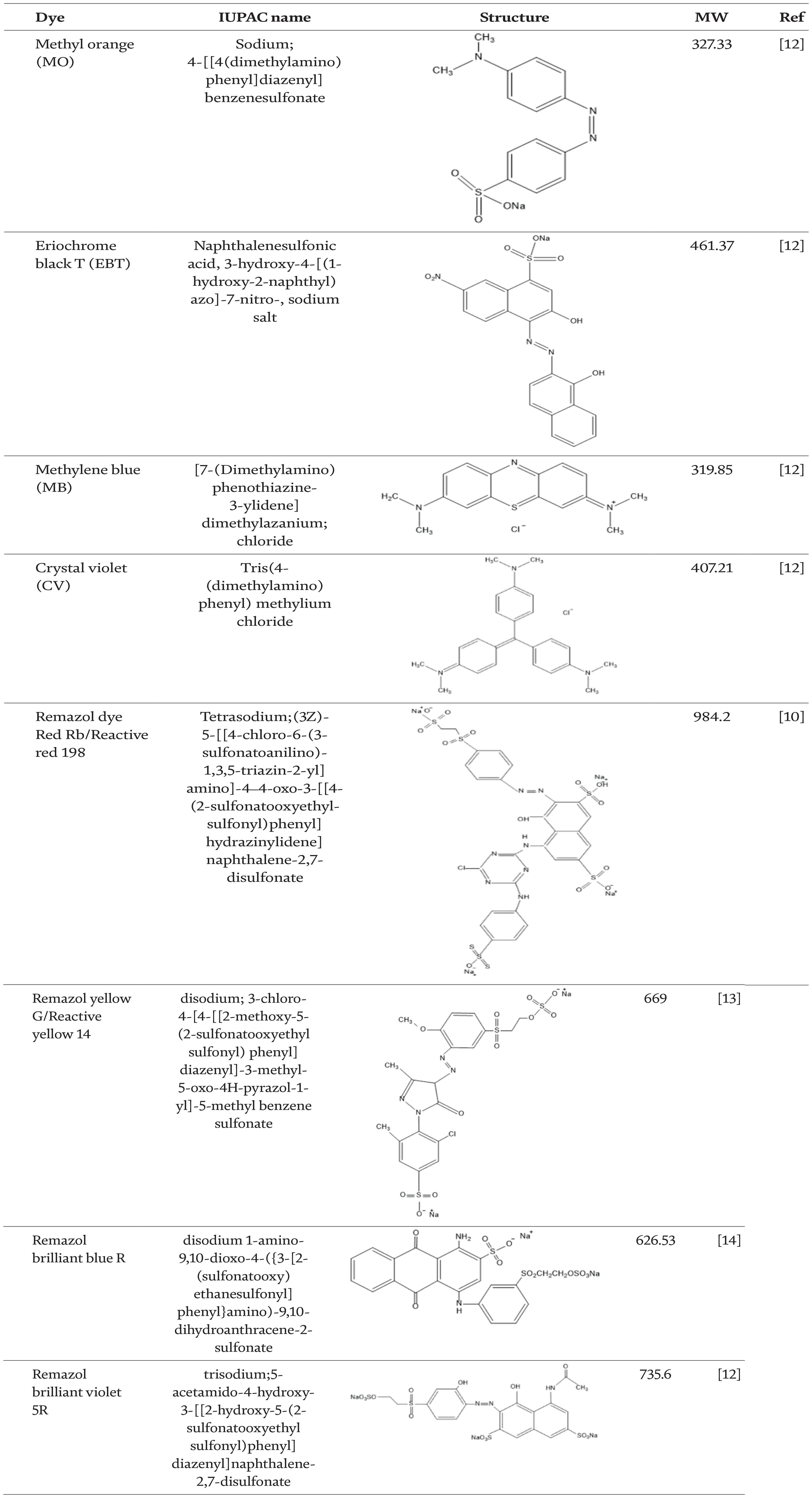
Charge is the primary distinction between cationic and anionic dyes. The molecules of cationic dyes are positively charged, whereas those of anionic dyes are negatively charged. Both cationic and anionic dyes are water-soluble. Cationic dyes include Crystal violet, Methylene blue, Basic blue, and Basic red [7, 8]. Methyl orange, Remazol, Alizarin Yellow R, and Eriochrome black T (EBT) are anionic dyes [9]. Remazol dyes are categorized as reactive azo dyes because it forms an ester bond with the fiber when they bind to it [10]. The structures of various dyes can be found in Table 1. Chromophores and auxochromes are the basic components in dye molecules. The colors that are visible are the result of chromophores. Auxochromes, nevertheless, act to enhance the affinity for the fibers and facilitate the solubility of the chromophore in water [11]. Batik wastewater contains a high concentration of electrolytes, which makes it difficult for light to penetrate [10], particularly solar irradiation, a natural degrading agent. Moreover, the presence of batik dyes in aquatic environments can give rise to a multitude of adverse effects, such as respiratory issues, cancer, allergies, and ecological imbalances.
The term “photocatalysis” was used for the first time in 1911 to explain the effect of the illumination of ZnO on the bleaching of Prussian blue. The ZnO acts like a catalyst, which increases chemical reaction rate without getting consumed during the reaction process. Under ultraviolet (UV) light, Fujishima and Honda observed the phenomena of photocatalytic water splitting on a TiO2 electrode [15], opening a new world of possibilities to produce clean hydrogen.
The term “photocatalysis” refers to the use of a catalyst to speed up a photoreaction. Among these is photosensitization, a process in which an initial absorption of radiation by a different molecular entity known as the photosensitizer causes a photochemical modification in one molecular entity [16]. Depending on the particular photoreaction, the catalyst may interact with a principal photoproduct, the substrate in either its excited or ground state, or both to speed up the reaction. The schematic of photocatalytic processes is displayed in Figure 1. After the catalyst C absorbs the light, the sensitized photoreaction can happen in two ways: (i) through energy transfer by converting the reactant of interest, A, into an activated state that can be oxidized more readily than its ground state; and (ii) via electron transfer, by acting either as an electron donor or acceptor [17].
Figure 1.
The schematic of different photocatalytic pathway, C-catalyst, A-reactant (adapted from [17]).
The advantage of photocatalysis over traditional or current technologies [18] are as follows: (1) with the ability to use renewable and pollution-free solar energy, photocatalysis offers a good substitute for the energy-intensive conventional treatment procedures (adsorption, ultrafiltration, reverse osmosis, coagulation by chemical agents, and ion exchange on synthetic adsorbent resins); (2) unlike traditional treatments that move contaminants from one phase to another, photocatalysis produces harmless products; (3) a range of dangerous substances in various wastewater streams can be destroyed via the photocatalytic method; (4) photocatalysis requires little chemical input, mild reaction conditions, and a short reaction time; and (5) it can be used with hydrogen and produces little secondary waste.
As it offers exceptional advantages, for the past 40 years, the development of photocatalysis technology has progressed rapidly in term of materials and application. Furthermore, it will become very attractive as the process can be widely used in various applications such as degradation of organic contaminants in water, removal of metallic and other inorganic pollutants, recovery of valuable metals and chemicals, water disinfections and bacterial removal, purification and disinfection of air, hydrogen generation, functional materials including self-cleaning and anti-reflective material, and new synthetic routes for chemical processes [19].
4. Photocatalysis for degradation of organic pollutant
Nowadays almost all human activity discharges a wide variety of contaminants into the environment. There are approximately 30,000 chemicals commercially available with less knowledge of their occurrence and fate in the environment. Not to mention newly emerging micro-pollutants (e.g., pharmaceuticals, antibiotics, and pathogens) that are now easily being detected in the environment. The biggest challenge is the industrial dyes and textile dyes, which have been a long-term environmental threat. During the production process, 10–20% of all dye products produced worldwide are lost in textile wastes and discharged into aquatic bodies as effluents. Organic dyes are one of the leading groups of pollutants released into wastewaters from textile and other industrial processes [18].
Advanced oxidation processes (AOPs) such as ozonolysis, ozone/H2O2 peroxide process, UV/ozone, UV/H2O2, Fe2+/H2O2 Fenton process, irradiation with electrons, vacuum ultraviolet and ultrasonic, photocatalysis, and combinations of the stated methods have been extensively explored to mitigate a great variety of pollutants present in various environmental media. Numerous studies have focused on photocatalysis using different semiconductor materials in recent years. Hydroxyl radicals (•OH) are produced during the photocatalytic oxidation process when the catalyst is exposed to light. Organic materials therefore mineralize into CO2, H2O, and inorganic components [20].
Photocatalytic reaction primarily depends on photon energy and the response of catalysts. Semiconducting materials are characterized by a filled valence band, a vacant conduction band, and a band gap between two bands.
If a semiconducting material acts as a catalyst, it will perform as charge sensitizers by the irradiation of light and stimulate the redox process. The fundamental steps in the process of semiconductor photocatalysis are shown in Figure 2. An electron from the valence band is excited to the conduction band when light strikes the photocatalyst surface and the energy of the incident light is equal to or greater than the photocatalyst bandgap energy. This results in an excess of negative charge in the conduction band, e−, and an electron deficiency or hole, h+, in the valence band. They can participate in redox reactions and are equivalents of oxidizing and reducing agents, respectively. Any organic species that is adsorbed on the semiconductor’s surface could undergo sequential oxidation and reduction processes with these holes and electrons to produce the required products. [21]. Photocatalysts such as TiO2, ZnO [22], Fe2O3 [23], CdS [24], WO3 [25], Cu2O [26], and ZnS [27] have been used to effectively break down a variety of organic contaminants. TiO2 is the most often utilized photocatalyst among those semiconductors because of its strong photocatalytic activity, high stability, non-toxicity, and affordability when employed in the wastewater treatment industry [28].
Figure 2.
The schematic of semiconductor photocatalytic mechanism.
In order to achieve greater activity and outperform TiO2-based photocatalysts, new photocatalytic materials with unique compositions and structures are being thoroughly investigated. But there aren’t many examples of successful practical applications. From the technical and economical point of view, alternative photocatalytic materials that are as “good” as TiO2 are hard to find. One of the most viable and practical approaches in developing better photocatalysts remains the modification of TiO2 in various methods (e.g., impurity doping, sensitization, surface modification, integration with other nanostructured materials) [29].
5. Basic structures and properties of TiO2 semiconductor
Since the water splitting breakthrough using semiconductor reported by Fujishima and Honda in 1972 [15], titanium dioxide (TiO2) has been thoroughly studied as a potentially useful material in a variety of study domains, particularly those pertaining to the environment and energy [30]. TiO2 is a transition metal oxide semiconductor with three distinct polymorph crystalline structures, namely rutile, anatase, and brookite. Each structure has distinctive parameters, which contribute to the different physical and chemical properties. The size and crystal structure of the particles determine how stable a certain phase of TiO2 is. The most stable phase for particles larger than 35 nm is rutile. For nanoparticles smaller than 11 nm, the most stable phase is anatase. When it comes to microparticles in the 1135 nm range, brookite is most stable. Bulk rutile, anatase, and brookite have band gaps of 3.0, 3.2, and 3.14 eV, which implied its photon absorption capability in the wavelength smaller than 431, 387, and 395 nm, respectively [31]. It has been discovered that the anatase form offers the best properties for photocatalytic oxidation. When compared with rutile TiO2, the anatase has greater photocatalytic activity. One argument that could apply is the fact that anatase shows a smaller indirect band gap than direct band gap. Indirect band gap semiconductors typically have longer charge carrier lifetimes than do direct gap semiconductors [32].
In order to initiate the inter-band transition of electrons between the lowest unoccupied molecule orbital (LUMO) and the highest occupied molecule orbital (HOMO), the photocatalytic reaction needs a minimum photon energy that is greater than TiO2’s band gap. The photo-excited electrons are de-excited via multiple pathways following irradiation: (i) they recombine with holes on the semiconductor surfaces; (ii) they recombine with holes in the bulk volume; (iii) they are transferred to the absorbed organic/trapped or inorganic redox species (typically oxygen molecules in the aerated solution); and (iv) the holes migrate to the surfaces and receive electrons from the absorbed redox species via oxidation reactions. TiO2 is a semiconductor with a wide bandgap (3.0–3.2 eV) that requires the excitation light wavelength range shorter than ca. 400 nm (Eg = hc/λ ≈ 1240/λ) [29].
The overall photocatalytic process including the reduction-oxidation with its surrounding component can be divided into the following steps and described further in Eqs. (1)–(12) [29]:
TiO2+hv→TiO2(eCB−+hVB+)E1
TiO2(hVB+)+H2O→TiO2+H++OH⋅E2
TiO2(hVB+)+OH−→TiO2+OH⋅E3
TiO2(eCB−)+O2→TiO2+O2⋅−E4
O2⋅−+H+→HO2⋅E5
HO2⋅+HO2⋅→H2O2+O2E6
TiO2(eCB−)+H2O2→OH⋅+OH−E7
H2O2+O2⋅−→OH⋅+OH−+O2E8
H2O2+hv→2OH⋅E9
Organic compound+OH•→degradation productsE10
Organic compound+TiO2(hVB+)→oxidation productsE11
Organic compound+TiO2(eCB−)→reduction productsE12
A semiconductor’s surface undergoes photocatalytic processes when photons are absorbed, which can lead to the breakdown of organic molecules or the splitting of water. Because of its ability to gather photons, it can be used to degrade organic molecules, remove contaminants from a variety of media, and oxidize or reduce materials to generate hydrogen and hydrocarbons.
The performance of TiO2 photocatalytic activity is commonly measured by the reaction rate of the degradation process. In general, the degradation of photocatalysis proceeds according to pseudo first-order reaction kinetics. Prefixing the order of a reaction with “pseudo-” has become commonplace since, in actuality, one of the reactants in catalytic systems functions as a catalyst while maintaining its concentration constant. In a similar vein, when the substrate is present in considerable excess, it completely covers the catalyst surface, and its disappearance becomes mostly concentration dependent. A pseudo zero order photocatalytic process will be seen with such saturation coverage [33]. Because the concentration of adsorption in the dark is so small, the Langmuir-Hinshelwood model is frequently employed to describe and analyze reaction kinetics.
Both organic and oxygen molecules must participate in the photocatalytic destruction of organic contaminants. Since oxygen is usually in high concentration, its concentration during photocatalysis can be thought of as constant. The photocatalytic rate, as per the law of mass-action, can be represented as [34]:
r=−dC(t)dt=kC(t)E13
where k is the rate constant, and C(t) is the concentration of reactants that adsorb on the semiconductor surface at time t. Photocatalysis requires the adsorption of organic materials on the semiconductor surface. It is believed that the adsorption-desorption (A–D) equilibrium complies with a Langmuir isotherm. However, in typical photocatalytic circumstances, the organic concentration is typically quite low, therefore the Eq. (13) can be simplified to:
lnC0Ct=ktE14
where C0 is initial concentration of organic substances before photocatalysis, and Ct is the reactive concentration at time t during the photocatalytic reaction. Eq. (14) can be easily used to calculate the k of different photocatalytic reactions.
Numerous factors and operational parameters affect the efficiency of photocatalytic processes, particularly when it comes to organic degradation. After a thorough analysis of the key factors, it was determined that the initial reactant concentration, light wavelength, feed flow rate, irradiation time, and pH had decreasing effects on process performance, while the increase in dissolved oxygen, light intensity distribution, photocatalyst loading to some extent, and air flow rate had increasing effects [32]. The execution of TiO2 photocatalysis technology in the wastewater treatment application requires more research and development especially in the process and kinetics aspects of the photocatalysis itself. Several types of photocatalytic reactors have been proposed and investigated for the last 20 years, which can mainly be divided into two categories according to the catalyst form: (i) TiO2 immobilized on support materials, e.g., quartz sand, glass, glass wool matrix, ceramic or polymer membranes, noble metal etc., and (ii) TiO2 suspended in aqueous medium [32]. Even though it has a high operating cost and necessitates additional treatment after the degradation process, the TiO2 suspended reactor has a higher photocatalytic area to reactor volume ratio, higher mass transfer and degradation efficiency, fairly uniform catalyst distribution, and an adjustable amount of nanoparticle suspension in the reactor to deal with different compositions of treated solution. In the meantime, TiO2 immobilized reactors do not require catalyst separation or recycling, and their degrading efficiency is lower than that of suspension mode. Additionally, they cannot have their catalyst loading adjusted to address [35].
Several different reactors were designed such as novel tube light reactor, multiple tube light reactor, fluidized bed photoreactor, fixed bed photocatalytic reactor, batch photoreactor, slurry continuous flow reactor, hexagonal annular photoreactor; spinning disk photoreactors; solar photocatalytic reactor; annular photocatalytic reactor, and tubular photocatalytic reactor, etc. Some of them are designed with the suspended type of catalyst and the other using immobilized catalyst within the reactor [32]. From the technical application point of view the immobilized TiO2 is preferred because, following the photocatalytic process, it does not require any additional post-treatment for the recovery of catalyst particles. On the other hand, films containing immobilized TiO2 powders had issues with the catalyst particles’ detachment. Furthermore, a portion of the porous structure is lost through the sintering process during the heating procedure that fixes the photocatalyst. They result in inefficient mass transfer by decreasing the photocatalyst’s area-to-volume ratio. As a result, there appears to be a factor of 10 difference in the efficiency of reactors with immobilized photocatalysts compared to those with dispersed TiO2 particles (slurry) [32].
The overview of the photoreactor with the optimized parameters is summarized in Table 2. The photocatalytic activity of TiO2 is a multifaceted function that relies on the physical characteristics of the particles. Types of dye’s component to degrade are more profound to be the driving force of the optimum degradation rather than the design of the photocatalytic reactor.
Photoreactor System
Optimal Condition
Photodegradation Performance
Ref.
Characteristics: a pilot-scale falling film photoreactor (FFR) in slurry mode has a surface area of 60x120 cm and is tilted at 35° (local latitude)
Light Source: genuine solar light (35 W)
Scale: 25 L
Pollutant: 10 ppm
Catalyst: 100 ppm
Light Intensity: 1.1 mW/cm2
pH: 2 (2–10)
Oxidating Agent: 10 mM H2O2
Stirring/Flow rate: 30 L/h
Pollutant: Methylene Blue
Catalyst: Pure TiO2, and 1 wt.% Ag/TiO2 (by the simple chemical reduction)
8. Continuous tubular photoreactor with TiO2 nanoparticles catalyst for batik industrial wastewater treatment
8.1 Continuous tubular photoreactor prototype
A continuous tubular photoreactor prototype has been developed as shown in Figure 3. The system consists of five photoreactor tubes that are designed to allow fluid to flow either in parallel or in series depending on the ball valve that is mounted on the pipe. The box panel is a place where all the buttons to turn on or turn off system parts are stored. The frame serves as a structural support for all the equipment and is made from hollow pipe of ST 42 steel. The frame’s primary dimensions are 1200 × 365 × 1700 mm (l × w × h), and it has four roller wheels at the bottom to facilitate system mobility. The feed tank with dimensions of 600 × 300 × 300 mm (w × w × h) is made of 304 stainless steel plate with a thickness of 1 mm. It also has a glass cover on the front to make it easier to watch during the process. Polyvinyl chloride (PVC) pipes Sch 40 with a 1/2-inch diameter are used in the fluid flow system. These pipes are connected using elbow pipes at the ends and tee pipes at each intersection with the same diameter and thickness. Two primary valves are positioned at the end of the flow output and close to the pump. There are also sixteen ball valves to control the flow whether operating in series or parallel. A flowmeter tube with an 18 L/min capacity is mounted on the system’s top side.
Figure 3.
Continuous tubular photoreactor system.
The tubular photoreactor is made of 304 stainless steel, 90 cm in length and 3/4 inch in diameter with capacity 12 gallons per minute. Inside it is fitted with a UV light with a power of 40 Watt, which is shielded by a glass sleeve of 85 cm. When the main valve and pump are turned on, the solution will flow into the photoreactor. The solution flow rate is controlled with a flowmeter.
The lower the flow rate, the longer the flow will stay in the photoreactor, and the higher the flow rate, the faster the flow will exit the photoreactor. If the system is run in series, the solution will enter photoreactor 1 and photocatalytic activity will occur in the tube. Once the solution exits photoreactor 1, it proceeds to photoreactor 2 for the same procedure, and so on, until the solution reaches photoreactor 5. This system also can run in parallel. The solution will enter simultaneously into photoreactors 1, 2, 3, 4, and 5. Photocatalytic activity also occurs simultaneously in each tube photoreactor.
8.2 Continuous tubular photoreactor performance
Methylene blue solution as a representation of batik waste was run in series on a continuous tubular photoreactor with flow rate and catalyst loading variation. The initial concentration was 10 ppm, and to make sure that photocatalysis was the only factor contributing to the degradation process, the adsorption was performed for 30 minutes before the photocatalytic process began. Photocatalysis is carried out until a color change occurs in the solution, and every 30 minutes the solution is taken to analyze the remaining methylene blue concentration. The catalyst loading used is 0.25; 0.50; 0.75; 1 g/L and from that the best performance of the photodegradation was carried out by catalyst loadings of 0.75 and 1.00 g/L with almost complete degradation up to 97% (Figure 4). The degradation process was completely achieved in 30–60 minutes with the highest kinetics rate 0.059/min calculated using pseudo-first-order kinetics from the Langmuir-Hinshelwood model, which can be used to explain the reaction kinetics of methylene blue photodegradation (Eq. 14) as mentioned in previous section.
Figure 4.
The methylene blue degradation profile and kinetics constant of photocatalysis using TiO2 nanoparticles at different catalyst loading.
The optimum catalyst loading in every system varies depending on the reactor and position of the photon source. Thus, in every system it has optimum catalyst as adding too much catalyst dose can cause dispersion, thereby reducing the effectiveness of the UV lamp from entering the solution. TiO2 has super hydrophilic properties when irradiated by UV light [40, 41, 42]. In addition, hydrophilic substances function effectively with alcohol and water, whereas hydrophobic substances function optimally with ester and alkane substances [43].
In this study, methylene blue was dissolved into distilled water, so it can maximize the performance of TiO2 by photo induction. Nevertheless, the TiO2 surface can exhibit hydrophobic characteristics under certain conditions when exposed to visible or ultraviolet light; this transformation is reversible [44]. The same as Shondo et al. who conducted research on modification of the Au-TiO2 surface with octadecyl-phosphonic acid (ODP) self-assembly monolayer produce extraordinary water repellent, they found the contact angle (CA) of the catalyst was < 5° and it became CA > 163° by means the substance changes from hydrophobic to hydrophilic during photocatalysis and it is strongly influenced by light intensity [41, 45]. In addition, the diffusion of products and reactants is influenced by the wettability of the catalyst surface. In addition to catalyst loading, different flow rates ranging from 1 to 9 L/min were used to study the degradation profile of methylene blue, which serves as a proxy for Batik dye wastewater. The result demonstrates that the fastest degradation was attained at a flow rate of 3 L/min, with a degradation kinetics constant of k = 0.01762/min (Figure 5).
Figure 5.
The methylene blue degradation profile and kinetics constant of photocatalysis using TiO2 nanoparticles at different flow rates.
Several factors do influence photocatalysis such as light intensity, temperature, pH, pollutant concentration, and catalyst loading. Besides that, flow rate is one of the driven parameters in the photodegradation process on tubular photoreactor at a certain level. Previous experiments show that at low flow rate (less than 0.6 L/min) the TiO2 nanoparticle tend to sediment in the lower side of the photoreactor [46]. While higher flow rate not only gives good suspension of TiO2 nanoparticles in the methylene blue solution but also led to maximum contact as well as optimum opacity for the UV light to penetrate and activate the TiO2 surface for photodegradation. When the number of active sites on the catalyst increases, decolorization of MB occurs. The formation of hydroxyl and superoxide as active radicals is the key point driving the degradation reaction [47]. In this system, flow rate of 1 L/min is considered a low flow rate. Sedimentation of TiO2 nanoparticles occurs at the bottom side of the tubular photoreactor, so that the amount of TiO2 that is active as a catalyst in photocatalysis is reduced. While the optimal TiO2 nanoparticle for methylene blue degradation is achieved at a flow rate of 3 L/min, this also leads to the maximum contact time and optimum opacity for the UV light to penetrate and activate the TiO2 surface for photodegradation. Given that the photodegradation rate, or k value, is lower than the rate attained by the 3 L/min, high flow rates (6–9 L/min) may have different impacts.
High flow rates have the potential to cause the suspension to turbulence, which can disrupt both the reaction and penetration of UV radiation. Additional research on the effects of flow rate (2–10 L/min) in disinfection-based photocatalysis reveals that the process is more effective at lower flow rates (2 L/min) because applying a high flow rate could cause mechanical stress and disrupt the process’s light flow and sequence [48].
8.3 Degradation of batik wastewater
The developed continuous tubular photoreactor is also used to treat batik wastewater from the batik industry in Semarang, Indonesia. The wastewater consists of Remazol Brilliant Blue, Remazol Yellow, Remazol Brilliant Violet, and Remazol Red. Like Remazol, reactive azo dyes are frequently used to color cloth fibers. Remazol yellow’s presence of peaks at 259 and 420 nm, whose wavelengths match the color of the substance’s UV–VIS spectrum, serves as evidence [49]. Then, Remazol Brilliant Violet or Remazol Brilliant Blue most likely owns the peak at 564 nm [50]. Over time, the absorbance of batik wastewater decreases. Batik wastewater’s initial absorbance values were 0.844, 0.537, and 0.203 at wavelengths of 259, 420, and 564 nm, respectively.
The result shows that dyes contained in the solution were no longer detectable within 4 hours. The Remazol Brilliant Violet or Remazol Brilliant Blue degraded within 60 min at a kinetics constant of 0.0065/min, followed by Remazol yellow degraded within 3.5 hours at 0.0037/min of kinetics constant. Smaller organic contaminants containing water and oxygen molecules are produced by this photocatalytic breakdown [51], making them safer for the environment. The most efficient batik waste degradation was observed 30 minutes after the adsorption process. This was also seen by Ariyanti et al. [48] who demonstrated that practically all RhB could be degraded at a catalyst dosage of 0.5 g/L once adsorption conditions were met for a maximum of 15 minutes (Figure 6).
Figure 6.
UV–visible spectrum and visualization of batik wastewater after photocatalysis.
In photocatalytic reactions, electrons from the valence band are excited to the conduction band, producing electron hole pairs (e−/h+) when photons with energy equal to or greater than the energy gap of semiconducting materials are absorbed [52]. When water molecules or hydroxyl ions (OH−) interact with photogeneration gaps (h+) in the valence band, free radicals are produced.
Conversely, excited electrons (e) in the conduction band combine with the oxygen in the solution to form superoxide radical anions (∙O2−) [52]. Then, superoxide radicals react with H+ ions to produce hydrogen peroxide, which breaks down into OH radicals. The production of reactive oxygen species during photocatalysis can trigger oxidation and reduction, which may lead to the chromophores in the azo-reactive dye being cleaved. Based on Figure 5.5(a), the chemical structure of azo dyes consists of the backbone, auxochrome groups, chromophores groups, and solubilizing groups [53, 54]. Chromophore (N〓 N) cleavage will result in the formation of intermediate amine compounds and sulfonic acid [55]. The batik wastewater becomes decolored as a result of the chain breaking caused by the insertion of protons and electrons in the diazo N〓N bond [56]. The azo linkages (N〓N) in the molecules are broken down by photocatalysis, which is involved in the breakdown of wastewater pollution. The process starts with the azo bond cleavage (N〓N) and continues with the cleavage of single and double bonds.
Breaking bonds with the lowest energy come first for initiators, then those with the highest energy. The degradation pathways for Remazol Yellow, Remazol Brilliant Blue, Remazol Red, and Remazol Brilliant Violet are shown in Figures 5.5(b-e). At the point where the bond energy is lowest, which is C∙S (259 kJ/mol), the bond breaks. Remazol undergoes C∙S bond cleavage throughout. All things considered, Remazol Yellow is the azo dye that degrades the slowest due to the occurrence of the bonds C〓N (615 kJ/mol) and C〓O (745 kJ/mol). Aside from that, other types of Remazol have more phi (π, electron transition) compared to Remazol Yellow. The decomposition of Remazol Brilliant Blue R and Remazol Yellow FG using doped TiO2 was also found in the research. The results show that the Remazol Brilliant Blue R decomposed more than Remazol Yellow [14].
The Implementation of TiO2 photocatalysis as one of advanced oxidation technology (AOP) for complete removal of organic pollutants such as dyes in wastewater is very promising. Many types and designs of photocatalytic reactors are developed; among them the tubular photocatalytic reactors have more technical visibility and economic viability to be implemented for Batik wastewater industry application.
Continuous tubular photoreactor with TiO2 nanoparticles catalyst developed for batik industrial wastewater treatment consists of five reactors arranged in parallel connected by a 1/2-inch pipe and equipped with a circulation pump, flowmeter, feed tank, panel box, and valve. This system has been tested for photocatalysis in series with nanostructured TiO2 of 0.75–1.5 g/L catalyst loading. The degradation of methylene blue reached more than 97% and the reduction of Remazol dye in batik wastewater achieved 61%. Another processing parameter that strongly influences the performance of photoreactor is the flow rate, and the flow rate of 3 L/min is the most effective condition for the degradation of dyes in wastewater with the kinetic constant of 0.01762/min. Degradation of dyes in wastewater is a challenge and improvement still needs to be address in terms of increasing the degradation rate as well as catalyst recovery.
Authors acknowledge Universitas Diponegoro, Indonesia for the research financial support.
References
1.Darmawanti T, Suhartana S, Widodo DS. Pengolahan Limbah Cair Industri Batik dengan Metoda Elektrokoagulasi Menggunakan Besi Bekas Sebagai Elektroda. Jurnal Kimia Sains dan Aplikasi. 2010;13(1):18-24
2.Agustina TE, Bustomi A. Pada Proses Pengolahan Limbah Pewarna Sintetik. Jurnal Teknik Kimia Universitas Sriwijaya. 2016;22(1):65-72
3.Indonesia SNR. Peraturan Pemerintah Nomor 22 Tahun 2021 tentang Pedoman Perlindungan dan Pengelolaan Lingkungan Hidup. Vol. 1. Jakarta: Sekretariat Negara Republik Indonesia; 2021
4.Jannah IN, Muhimmatin I. Pengelolaan Limbah Cair Industri Batik menggunakan Mikroorganisme di Kecamatan Cluring Kabupaten Banyuwangi. Warta Pengabdian. 2019;13(3):106-115
5.Rashidi H, Sulaiman NMN, Hashim NA, Bradford L, Asgharnejad H, Madani LM. Wax removal from textile wastewater using an innovative hybrid baffle tank. Journal of the Textile Institute. 2021;112(2):223-232
6.Almazán-Sánchez PT, Linares-Hernández I, Solache-Río MJ, Martínez-Miranda V. Textile wastewater treatment using iron-modified clay and copper-modified carbon in batch and column systems. Water, Air, and Soil Pollution. 2016;227(4):100
7.Salleh MAM, Mahmoud DK, Karim WAWA, Idris A. Cationic and anionic dye adsorption by agricultural solid wastes: A comprehensive review. Desalination. 2011;280(1-3):1-13
8.Demirbas A. Agricultural based activated carbons for the removal of dyes from aqueous solutions: A review. Journal of Hazardous Materials. 2009;167(1-3):1-9
9.Atas MS, Dursun S, Akyildiz H, Citir M, Yavuz CT, Yavuz MS. Selective removal of cationic micro-pollutants using disulfide-linked network structures. RSC Advances. 2017;7(42):25969-25977
10.Aryanti N, Nafiunisa A, Kusworo TD, Wardhani DH. Separation of reactive dyes using natural surfactant and micellar-enhanced ultrafiltration membrane. Journal of Membrane Science and Research. 2021;7(1):20-28
11.Solayman HM, Hossen MA, Abd Aziz A, Yahya NY, Leong KH, Sim LC, et al. Performance evaluation of dye wastewater treatment technologies: A review. Journal of Environmental Chemical Engineering. 2023;11(3):109610
12.Attallah OA, Al-Ghobashy MA, Nebsen M, Salem MY. Removal of cationic and anionic dyes from aqueous solution with magnetite/pectin and magnetite/silica/pectin hybrid nanocomposites: Kinetic, isotherm and mechanism analysis. RSC Advances. 2016;6(14):11461-11480
13.Ketut SD, Oktofa RD, Ketut S. Color removal of textile wastewater using indirect electrochemical oxidation with multi carbon electrodes. Environment Asia. 2018;11(3):170-181
14.Purnawan C, Wahyuningsih S, Aniza ON, Sari OP. Photocatalytic degradation of Remazol brilliant blue R and Remazol yellow FG using TiO2doped Cd, Co, Mn. Bulletin of Chemical Reaction Engineering and Catalysis. 2021;16(4):804-815
15.Fujishima A, Honda K. Electrochemical photolysis of water at a semiconductor electrode. Nature. 1972;238:37-38
16.Balzani V, Bergamini G, Ceroni P. Photochemistry and photocatalysis. Rendiconti Lincei. 2017;28:125-142
17.Castellote M, Bengtsson N. Applications of Titanium Dioxide Photocatalysis to Construction Materials. Switzerland AG: Springer Nature; 2011. pp. 5-10
18.Saravanan R, Gracia F, Stephen A. Basic principles, mechanism, and challenges of Photocatalysis. In: Nanocomposites for Visible Light-Induced Photocatalysis. Switzerland AG: Springer Nature; 2017. pp. 19-40
19.Li M, Lin HY, Huang CP. Nanotechnostructured catalysts TiO2 nanoparticles for water purification. In: Nanotechnologies for Water Environment Applications. VA, USA: American Society of Civil Engineers (ASCE); 2009. pp. 43-92
20.Ajmal A, Majeed I, Malik RN, Idriss H, Nadeem MA. Principles and mechanisms of photocatalytic dye degradation on TiO2 based photocatalysts: A comparative overview. RSC Advances. 2014;4(70):37003-37026
21.Nakata K, Fujishima A. TiO2 photocatalysis: Design and applications. Journal of Photochemistry and Photobiology C: Photochemistry Reviews. 2012;13(3):169-189
22.Hamdam Momen M, Amadeh A, Heydarzadeh Sohi M, Moghanlou Y. Photocatalytic properties of ZnO nanostructures grown via a novel atmospheric pressure solution evaporation method. Materials Science and Engineering: B. 2014;190:66-74
23.Ai Z, Gao Z, Zhang L, He W, Yin JJ. Core-shell structure dependent reactivity of Fe@Fe2O3 nanowires on aerobic degradation of 4-chlorophenol. Environmental Science & Technology. 2013;47(10):5344-5352
24.Fu X, Zhang Y, Cao P, Ma H, Liu P, He L, et al. Radiation synthesis of CdS/reduced graphene oxide nanocomposites for visible-light-driven photocatalytic degradation of organic contaminant. Radiation Physics and Chemistry. 2016;123:79-86
25.Mohite SV, Ganbavle VV, Rajpure KY. Solar photoelectrocatalytic activities of rhodamine-B using sprayed WO3 photoelectrode. Journal of Alloys and Compounds. 2016;655:106-113
26.Feng L, Zhang C, Gao G, Cui D. Facile synthesis of hollow Cu2O octahedral and spherical nanocrystals and their morphology-dependent photocatalytic properties. Nanoscale Research Letters. 2012;7:1-10
27.Sharma M, Jain T, Singh S, Pandey OP. Photocatalytic degradation of organic dyes under UV-visible light using capped ZnS nanoparticles. Solar Energy. 2012;86(1):626-633
28.Ola O, Maroto-Valer MM. Review of material design and reactor engineering on TiO2 photocatalysis for CO2 reduction. Journal of Photochemistry and Photobiology C: Photochemistry Reviews. 2015;24:16-42
29.Park H, Park Y, Kim W, Choi W. Surface modification of TiO2 photocatalyst for environmental applications. Journal of Photochemistry and Photobiology C: Photochemistry Reviews. 2013;15(1):1-20
30.Chen X, Liu L, Huang F. Black titanium dioxide (TiO2) nanomaterials. Chemical Society Reviews. 2015;44(7):1861-1885
31.Fujishima A, Zhang X, Tryk DA. TiO2 photocatalysis and related surface phenomena. Surface Science Reports. 2008;63(12):515-582
32.Zangeneh H, Zinatizadeh AAL, Habibi M, Akia M, Hasnain IM. Photocatalytic oxidation of organic dyes and pollutants in wastewater using different modified titanium dioxides: A comparative review. Journal of Industrial and Engineering Chemistry. 2015;26(December):1-36
33.Gaya UI. Heterogeneous photocatalysis using inorganic semiconductor solids. In: Heterogeneous Photocatalysis Using Inorganic Semiconductor Solids. Dordrecht: Springer Science + Business Media; 2014. pp. 43-71
34.Liu B, Zhao X, Terashima C, Fujishima A, Nakata K. Thermodynamic and kinetic analysis of heterogeneous photocatalysis for semiconductor systems. Physical Chemistry Chemical Physics. 2014;16(19):8751-8760
35.Ong CS, Lau WJ, Goh PS, Ng BC, Ismail AF, Choo CM. The impacts of various operating conditions on submerged membrane photocatalytic reactors (SMPR) for organic pollutant separation and degradation: A review. RSC Advances. 2015;5(118):97335-97348
36.Wetchakun K, Wetchakun N, Sakulsermsuk S. An overview of solar/visible light-driven heterogeneous photocatalysis for water purification: TiO2- and ZnO-based photocatalysts used in suspension photoreactors. Journal of Industrial and Engineering Chemistry. 2019;71:19-49
37.Akram TM, Ahmad N, Shaikh IA. Characterization and optimization of photocatalytic activity of sol gel-synthesized TiO2 and Ag-doped TiO2 through degradation of synthetic textile effluent by UV lamp-assisted experimental setup. Polish Journal of Environmental Studies. 2019;28(4):2571-2583
38.Damodar RA, You SJ, Ou SH. Coupling of membrane separation with photocatalytic slurry reactor for advanced dye wastewater treatment. Separation and Purification Technology. 2010;76(1):64-71
39.Yap WQ , Chin YH, Leong KH, Saravanan P, Sim LC. Design of photoreactor with high sunlight concentration for improved photocatalytic degradation of dye pollutant. IOP Conference Series: Earth and Environmental Science. 2021;646(1)
40.Kameya Y, Yabe H. Optical and superhydrophilic characteristics of TiO2 coating with subwavelength surface structure consisting of spherical nanoparticle aggregates. Coatings. 2019;9(9):547
41.Shondo J, Veziroglu S, Stefan D, Mishra YK, Strunskus T, Faupel F, et al. Tuning wettability of TiO2 thin film by photocatalytic deposition of 3D flower- and hedgehog-like Au nano- and microstructures. Applied Surface Science. 2021;537:147795
42.Zhang X, Jin M, Liu Z, Tryk DA, Nishimoto S, Murakami T, et al. Superhydrophobic TiO2 surfaces: Preparation, photocatalytic wettability conversion, and superhydrophobic-superhydrophilic patterning. Journal of Physical Chemistry C. 2007;111(39):14521-14529
43.Wei M, Kuang Y, Duan Z, Li H. The crucial role of catalyst wettability for hydrogenation of biomass and carbon dioxide over heterogeneous catalysts. Cell Reports Physical Science. 2023;4(5):101340
44.Stevens N, Priest CI, Sedev R, Ralston J. Wettability of photoresponsive titanium dioxide surfaces. Langmuir. 2003;19(8):3272-3275
45.Maeda H, Kobayashi T, Konishi S. Patterning of wettability using the photocatalytic decomposition of hydrophobic self-assembled monolayer on the TiO2 pattern. Japanese Journal of Applied Physics. 2017;56(6):2-6
46.Suryaman D. Titanium dioxide suspension photocatalysis in a tubular photoreactor and titanium dioxide reuse on the removal of phenol. Jurnal Air Indonesia. 2018;4(2):160-166
47.Abdellah MH, Nosier SA, El-Shazly AH, Mubarak AA. Photocatalytic decolorization of methylene blue using TiO2/UV system enhanced by air sparging. Alexandria Engineering Journal. 2018;57(4):3727-3735
48.Sichel C, Blanco J, Malato S, Fernández-Ibáñez P. Effects of experimental conditions on E. Coli survival during solar photocatalytic water disinfection. Journal of Photochemistry and Photobiology A: Chemistry. 2007;189(2-3):239-246
49.Bhuiyan MSH, Miah MY, Paul SC, Das AT, Saha O, Rahaman MM, et al. Green synthesis of iron oxide nanoparticle using Carica papaya leaf extract: Application for photocatalytic degradation of remazol yellow RR dye and antibacterial activity. Heliyon. 2020;6(8):e04603
50.Zainip VJ, Adnan LA, Elshikh MS. Decolorization of Remazol brilliant violet 5R and Procion red MX-5B by Trichoderma species. Tropical Aquatic and Soil Pollution. 2021;1(2):108-117
51.Mohammadi M, Sabbaghi S, Binazadeh M, Ghaedi S, Rajabi H. Type-1 α-Fe2O3/TiO2 photocatalytic degradation of tetracycline from wastewater using CCD-based RSM optimization. Chemosphere. 2023;336(May):139311
52.Shahid-ul-Islam BS, Kamali MR. Review on green biomass-synthesized metallic nanoparticles and composites and their photocatalytic water purification applications: Progress and perspectives. Chemical Engineering Journal Advances. 2023;14(January):100460
53.Benkhaya S, Cherkaoui O, Assouag M, Mrabet S, Rafik M, El HA. Synthesis of a new asymmetric composite membrane with bi-component collodion: Application in the ultrafiltration of baths of reagent dyes of fabric rinsing/padding. Journal of Materials and Environmental Science. 2016;7(12):4556-4569
54.Benkhaya S, M’rabet S, El Harfi A. Classifications, properties, recent synthesis and applications of azo dyes. Heliyon. 2020;6(1):e03271
55.Mazzanti M, Caramori S, Fogagnolo M, Cristino V, Molinari A. Turning waste into useful products by photocatalysis with nanocrystalline TiO2 thin films: Reductive cleavage of azo bond in the presence of aqueous formate. Nanomaterials. 2020;10(11):1-17
56.Rauf MA, Meetani MA, Hisaindee S. An overview on the photocatalytic degradation of azo dyes in the presence of TiO2 doped with selective transition metals. Desalination. 2011;276(1-3):13-27
Written By
Dessy Ariyanti, Dina Lesdantina, Ariana Aisa, Farida Diyah Hapsari, Filicia Wicaksana and Wei Gao
Submitted: 31 January 2024Reviewed: 04 February 2024Published: 30 April 2024