
Abstract
In the grinding of machine and responsible equipment parts, gear surfaces with various purpose shapes provided in the construction of tools, as well as gear surfaces, provide high processing accuracy and productivity. At this time, the positioning angles of the elemental regions of the workpiece to be ground in the cutting zone differ from each other, and the actual cutting depth varies along the shaped profile. Due to inheritance, similar processing errors occur on the ground surface, and processing efficiency is not ensured. In this work, the mechanism of the change in cutting depth during the grinding of shaped surfaces by copying is investigated, the direction of ensuring its maximum regularity along the shaped profile is determined, and the issue of improving the quality and efficiency of grinding is solved by using the technological possibilities of operation. Despite the reduction in the number of working trips, grinding should be carried out in relatively light modes, and it is possible to ensure similar grinding quality. By placing the tooth of the gear to be ground at an angle, the roughness of the processed surfaces during grinding is smaller than that of the tooth grinding with the existing method, and the quality is correspondingly high.
Keywords
- shaped surface
- grinding
- parameter
- minimum
- profile
- depth of cut
- different
- direction
- quality
- elevation
1. Introduction
Machinery and aviation equipment parts are provided for the construction of tools, and the surfaces are shaped according to the requirements of their functional purposes. For example, turbine blades, stamps, mold parts, etc.; surfaces; shaped chisels; shaped milling cutters; and roller tools used for rolling different profiles in sheet materials are similar [1, 2, 3, 4]. The working conditions of these surfaces require them to have high precision and surface qualities. Therefore, these surfaces are usually ground. Grinding of shaped surfaces by the copying method along the profile provides high processing accuracy and relatively high productivity. Grinding of shaped surfaces in various prismatic and rotational bodies by the copying method is widely used in machine building [1, 2, 4, 5, 6].
Grinding in serial production is carried out on CNC-type machines, using various copying arrangements, with a grinding circle with a rounded working surface. However, this method for copying is not efficient for mass and large series production. In mass and large-scale production, it is more efficient to grind rotary and flat surfaces with a grinding wheel that matches the shape of the profile to be shaped. For this purpose, circular grinding machines are used to grind rotating surfaces, and flat and flat copying grinding machines with rectangular tables are used to grind flat surfaces.
To grind the shaped surface by copying in the rotary parts, workpiece circle 3 is placed in centers 4 and 5 of the grinding machine, usually with its axis parallel to the axis of spindle 2 of the machine (Figure 1). Grinding is carried out with abrasive wheel 1, which is a copy of the profiled surface of the working surface. One high-frequency (

Figure 1.
Grinding of a shaped rotary surface by copying on a circular grinding machine.
Usually, for grinding, after lathe processing, a constant fixed allowance
During the grinding of shaped surfaces by copying, the change in the actual depth of cut in the elementary regions, imitating the change in the cutting mode, causes the following negative changes:
The thickness of the material layer removed by each abrasive wheel and the depth of cut are large relative to the machining allowance and vary in a wide range,
t2 = > max; (t2- t1) = > max (Figure 1),the working width of the abrasive wheel is smaller than the length of the shaped surface, (
H = > min ) [9, 13],the difference in the diameters of the elementary working cross-sectional limits of the abrasive wheel is large, (
(Dmax – Dmin) = > max ) (Figure 1),analogously to the actual depth of cut, since the tool wear on the working profile is proportional to the volume of material removed by the elementary regions, its unevenness is high,
tool wear intensity varies dramatically along the worker profile, (U
= > max ),The thickness of the abrasive layer removed in each sharpening of the tool is determined according to the region with the largest cutting depth and receives correspondingly large values (
Ut = > max ). That is, although the wear of the abrasive circle is minimal in the region with a relatively small depth of cut, more abrasive layers are removed from that region during sharpening.the sharpening frequency of the tool is high, and its service life is short, (
T = > min ) [8, 14],high heat is generated in the cutting region,
It becomes difficult to remove the released heat from the cutting region. Thus, the width and volume of the grinding wheel are very small compared to those of the shaped profile, and its contact area with the cooling-lubricating liquid is small.
favorable conditions for the occurrence of thermal burns are created in the upper layers of the processally shaped surface,
Different processing qualities are formed along the shaped profile and its length, and the grid quality and efficiency of the shaped surface are low.
These shortcomings have a negative effect on the accuracy and quality of ground surfaces. Therefore, to reduce similar negative effects due to sharp differences in the actual cutting depths perpendicular to the axis of the abrasive wheel in different regions of the shaped surface during grinding or to eliminate their influence on the quality of the ground surfaces, the axis of the grinding wheel in grinding shaped surfaces by copying should be changed. It is necessary to ensure that the condition of the shaped surface is grinded in such a way that the actual cutting depth variation ranges are minimized on the entire shaped surface, the width of the abrasive wheel is brought closer to the width of the processed shaped surface and its maximum, and the minimum difference between the working elemental-local limit diameters of the tool is minimized. Such a grinding scheme would create a basis for increasing the efficiency of grinding by copying and for ensuring that the roughness and quality of the ground-shaped surfaces are relatively high.
The purpose of this work is to determine and test the direction of improving the quality and efficiency of grinding-shaped surfaces by copying.
2. Development of measures to increase the efficiency of grinding shaped surfaces by copying
Based on the research, increasing the regularity of the cutting depth along the shaped profile is considered the direction of increasing the grinding efficiency of shaped surfaces by copying, reducing the shortcomings allowed in grinding within the technological capabilities of the grinding process.
To ensure the maximum regularity of the depth of cut along the shaped profile during grinding, let us examine the mechanism of its change.
Suppose that in the elemental region of the shaped surface with the smallest inclination, in the region around point A, the angle between the region tangential to the surface and the plane of rotation of the cutting abrasive grain is
In the region with the smallest inclination (around point A, the inclination of the surface is at an angle
Thus, the largest difference in cutting depths from expressions (1) and (2) is:
Therefore, the mass (volume) of the material removed from around point B with the elementary-unit width of the abrasive circle is greater than the mass (volume) of the material removed from around point A. Since the number of abrasive grains per unit cross-sectional area is constant at the same diameters of the cross-section of the tool, correspondingly, the cross-sectional wear in the area of point B of the circle is also greater than that in area A.
As the inclination of the shaped profile is large within its given width, the difference between the diameters of the largest
To clarify the relationship between the feed direction and depth of cut, assume that the feed direction is parallel to the axis of the rotating surface
The minimum change in the cutting depth (
The condition for ensuring the minimum change in the cutting depth in grinding by copying: the line lying on the shaped profile must be parallel to the axis of the grinding circle. In this case, the rotation planes of the cutting abrasive grains are ensured to be perpendicular to the line lying on the shaped turn profile (Figure 2; here,
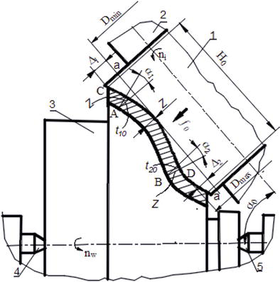
Figure 2.
Grinding scheme of a shaped rotary surface with the proposed copying method on a circular grinding machine.
In this case, as in the existing method of grinding shaped rotating surfaces.
In the developed method, grinding wheel 1 is placed on spindle 2 of the machine, and spindle 3 is placed on centers 4 and 5, but the spindle head is rotated by an angle α0 with respect to the axes of centers 4 and 5 (Figure 2). At this time, the angles between the direction
Therefore, in the grinding of shaped surfaces with the proposed method, the rotation angle α0 of the spindle head with respect to the axis of the workpiece and the correct selection of the direction of feed, ensuring its optimal
The feed is applied in the direction perpendicular to the axis of the tool to the line lying on the shaped profile. The turn angle of the spindle head, which determines the maximum regularity of the profile of the cutting depth, is determined by expression (4).
The grinding process is carried out as follows: grinding wheel 1 is driven with a high frequency (circumferential speed 30–80
Grinding of shaped surfaces with the proposed method also ensures a reduction in machine time compared to the existing method. Thus, the reduction in the grinding length
Here,
That is, the machine time decreases by (≈1/Cos α0) times. The reduction in machine time when grinding rotary surfaces with the proposed method is determined by expression (5) depending on the a–a position of the adjoining line.
3. Development of a method for grinding involute profiles of teeth in gear wheels by copying
One of the methods for grinding involute profiles of teeth in gear wheels is tooth grinding with high-productivity copying. Technological operation is carried out according to the scheme of grinding flat-shaped surfaces [1, 2, 4, 6].
It is known that to grind the teeth in gears by copying, they are placed almost vertically in the grinding area and ground [2, 6, 15]. It has been established that, analogously to shaped turning surfaces, the actual cutting depth determined in the vertical direction in a tooth grind with copying varies along the involute profile of the tooth [9, 13]. The examination of the tooth grinding scheme with copying shows that although the allowance

Figure 3.
Schematics of the influence of the location of the tooth in the grinding area in the vertical (1) and relatively horizontal (2) positions on the depth of cut along the involute profile (1 and 2) and the width of the grinding wheel (3 and 4).
As the inclination-horizontality of the involute profile in the grinding zone increases, the cutting depth decreases and becomes relatively regular distributed on the profile (Figures 1–3) (
One of the problems of machining processes with abrasive tools is the generation of high temperatures in the cutting area and the issue of removing the generated heat [2, 6, 16, 17]. In profile grinding with copying, the working width of the abrasive wheel is shorter than the length of the ground surface (Figures 3 and 4). As shown in the figure, depending on the state of the profile, the active working width of the grinding wheel changes during copying grinding. As the slope of the profile to be ground increases (for example,

Figure 4.
Proposed parallel grinding scheme of involute profiles of two inclined teeth.
It is recommended by the authors to parallel grind the different sides of the two teeth of the gear wheel, which are oppositely symmetrical and inclined with respect to the vertical symmetry plane, with two grinding wheels at the same time (Figure 4; where n is the number of teeth with optimal inclination, (n-1) and (n + 1) are the number of teeth before and after the optimal tooth, A is the distance from the symmetry plane to the grinding wheel, and b is the safety distance). At this time, ensuring the greatest possible inclination of the ground profiles, as mentioned, lays the foundation for ensuring high efficiency.
As shown in the diagram, as the inclination of the teeth increases, the gap between the side of the abrasive wheel and the neighboring tooth in front decreases, and the nonworking side surface of the circle approaches the profile of the front tooth. Therefore, the inclined tooth to be ground can be in such a position that the abrasive wheel touches the front tooth and damages it. Therefore, the parallel grinding of the two teeth with the largest inclination, which allows grinding along the entire length of the shaped involute profile while not damaging the profile of the front tooth of the tool, is convenient from both an economic and technological point of view.
The symmetrical placement of parallel grinding teeth in the grinding zone with respect to the plane of symmetry arises from the requirement of ensuring the efficiency of the technological process. In this case, the working conditions of the grinding wheels are ensured, their corrosion resistance is the same, and the efficiency of their profiling and sharpening is ensured. The solution to the problem should satisfy the following two main requirements:
The grinding of the profile should be ensured along the entire length of the involute from its starting point to the top circumference of the tooth.
The side of the grinding wheel should not cut the profile of the adjacent tooth. For this, a safety distance δ must be provided between the involute profile of the adjacent tooth and the side of the grinding wheel (P plane), δ
=1.5–2 mm (Figure 4).
Considering the above, to ensure the efficiency of tooth grinding with the proposed method, the number of rows of teeth rotated by the maximum angle
It should be noted that sometimes the crown part of the teeth is modified, and the working profile of the tooth differs from that of the involute tooth. However, the cost of the modification is very small, and it does not have a decisive effect on determining the optimal number of rows of bevel teeth. Nevertheless, if necessary, it can be taken into account in the value of δ.
In the grinding of teeth with existing and proposed methods, at any
A graph of

Figure 5.
Generalized diagrams of (1) allowance for grinding the profile, (2) depth of cut when processing a tooth located vertically, and (3) depth of cut when processing a tooth located with an optimal inclination depending on the involute angle.
In this case, the grinding wheel cuts the body of the adjacent tooth.
Using the extracted depth of cut equations, the extreme (limit) values of the depth of cut were determined when grinding the 1st and 5th teeth on a gear wheel with module
Thus, increasing the inclination of the grinded tooth in the grinding zone reduces the actual depth of cut, increases the working width of the abrasive circle, and reduces the volume of material removed with each element cutting width.
When grinding the involute profiles on the teeth with the greatest technologically possible inclination, located on the right and left sides of the vertical symmetry plane of the gear wheel, the minimum value of the cutting depth and the maximum regularity of its distribution are ensured, and the reduction in the cutting depth creates a condition for reducing the machine time by controlling the technological operation.
One of the problems of machining processes with abrasive tools is the generation of high temperatures in the cutting area and the removal of the generated heat [16]. To ensure the efficiency of teeth grinding with copying, this issue should also be resolved.
4. Reducing the total power of heat separations
The mechanism of material removal in the grinding of tooth surfaces by copying generally follows the scheme of grinding flat surfaces. Therefore, considering the characteristics of tooth grinding by copying, the results of existing research on the grinding of flat surfaces can be applied to the grinding of involute profiles of teeth.
One of the conditions for ensuring high processing quality with cutting is the favorable regulation of the thermal regime in the technological subsystems. The grinding process requires high precision and surface quality. Therefore, it is of particular importance to control and reduce the local and general heat characteristics of the technological process.
The empirical dependence between the cutting mode elements and the total heat dissipation power in the grinding of flat surfaces is expressed as follows [16]:
Here, the total power of heat released during grinding
During tooth grinding, the thickness of the removed material layer (a) is controlled to reduce the power of the heat released in the cutting area. The grinding conditions of the other organizers were unchanged.
The surface processed in tooth grinding is a flat-shaped profile. As mentioned, to reduce the range of variation in the actual depth of the cut along the profile during toothing, to ensure the minimum cutting depth-machining share on the plane of rotation of the abrasive grain, inclined teeth are ground. In this case, the thickness of the removed layer decreases as a result of turning the base tooth from the vertically located tooth by an angle
is taken. Here,
is taken. Thus, the ratio of the initial total power of heat separation to the total power after the technological measure is called the coefficient of reduction of heat separation power,
is taken. Here, by writing the value of
5. Conducting experiments and discussing results
To test the ability of the developed technology to increase the efficiency of grinding shapes, including gear surfaces, by copying, studies were conducted on different machines and gear wheels of different sizes. All the results obtained were positive. Here, we present some of them.
Number of teeth
Z = 40, modulem = 4mm , length of teethl = 44mm , gear wheel with material steel 40XH, [8] material hardness HRC 49–52,The number of teeth is
Z = 32, the modulem = 5mm , the tooth lengthl = 45mm , the hardness of the core material is 342–368 HB, and a gear wheel made of 12ХН3А steel is used [14].
As a test object,
In the first variant, the profiles of the teeth of the gear wheel are in a vertical position, facing each other (method applied in current production) (Figure 3). (1), and in the second variant, the profiles of the teeth located at a position rotated by a certain angle
The grinding process was carried out with two rough and two clean passes. The width of the feed in the radial direction was 0.100
The quality parameters of the gear surfaces were as follows:
The roughness of the gear surfaces of the ground samples was measured under both laboratory and production conditions. Measurements were carried out using a TR220 portable roughness tester and a БВ-7669 M profilograph-profilometer (Figure 6b).

Figure 6.
Measuring the roughness of the involute profile surface on the tooth: Measurement points (a) and measurement points (b).
Surface roughness parameters with the TR220 device: average profile deviation
In addition, the quality of the surface layer was also studied.
The results obtained from the experiments for the

Figure 7.
Change in surface roughness indicators (Ra və Rmax) along the involute profile of the tooth: 1- proposed method, 2- grinding with the traditional method.
The comparison of the roughness qualities of the surfaces obtained from polishing carried out by both options in all the samples confirms the results of the theoretical studies. In all cases, the roughness indicators of the surface ground by the proposed method were relatively small. That is, the grinding of inclined teeth ensured relatively high geometric qualities of the processed surfaces.
According to the theoretical provisions, the surface roughness parameters (
Since the depth of cut is relatively large in the regions near the bottom of the tooth, relatively large values of the roughness indicators are also observed in these regions. Thus, while
The results obtained from the experiments on the grinding of inclined teeth at the maximum height of roughness are presented in Figure 7b. The average value of parallel measurements of the largest height of profile roughness was
When grinding a tooth located vertically with the current method, the average value of the largest height of the profile roughness according to parallel measurements was
Similar results were observed for the average
As shown in the pictures, the change in roughness parameters along the profile occurs according to parabolic dependences. This regularity is explained by the regularity of the change in cutting depth along the involute profile. Although the regularity of the change in cutting depth has a direct effect on the roughness parameters, the resulting cutting conditions, cutting force, elastic–plastic and thermal deformations occurring in the cutting regions, variety of physical-mechanical-chemical processes, relatively high-temperature heat, lack of favorable heat transfer conditions, etc., all of which are indirect effects are inevitable. As a result, different quality indicators of ground surfaces are formed.
Thus, the grinding of shaped surfaces with a curved profile by ensuring the maximum inclination of the elementary regions in the grinding zone lays the groundwork for the minimum roughness of the processed surface. In addition, by grinding the tooth as much as possible, grinding with copy transfer ensures that the quality indicators of the roughness of its working surfaces increase up to 36.5% compared to tooth grinding with the existing method.
The number of trips plays a special role in processing quality and efficiency. Therefore, similar experiments should be conducted, and the reduction in the number of departures should be justified from both technical and economic points of view. Thus, by comparing the obtained results in terms of the number of passes and depth of cut in copying and grinding, it was determined that the grinding mode with the proposed method is lighter than the four-pass grinding with the traditional method. That is, in this case, there are conditions for satisfying the unevenness requirements of the involute profile. At the same time, the machine time spent grinding teeth is likely to be substantially reduced.
One of the methods for grinding involute profiles of teeth in gear wheels is tooth grinding with high-productivity copying. The technological operation is carried out according to the scheme of grinding flat-shaped surfaces.
According to the second option, tooth grinding was performed in two stages on a Gleason Pfauter P400G bench. To determine and compare the possibility of providing high precision, only one side of the tooth profile was ground. For comparison, after cutting the teeth with a hob cutter, all the studied parameters of the samples were measured.
In the first stage, the profiles of the teeth to be ground are brought to a vertical position according to the method used in production. The grinding process was carried out with two coarse and two fine passes. The radial depth of the cut was 0.10
In the second stage, according to the proposed method, the profiles of the teeth in the inclined position are rotated to the maximum possible angle relative to their vertical position, and the teeth located on the right and left relative to the vertical plane of symmetry are processed. Compared to the first stage, the actual depth of the cut section is reduced by more than 50%. The grinding process was carried out in two rough passes and one clean pass. The depth of cut was 0.18
Quality control of the grinded teeth was carried out in the Gleason 650GMS tooth analytical control system (tooth thickness, step, length of the general normal, profile shape, diameter of the division circle, and surface quality (roughness parameters, microhardness), etc.).
By studying the parameters of accuracy and surface quality, it was determined that the thickness and step accuracy of the tooth are ≈9–18%, the accuracy of the involute profile is ≈10–22%, the diametral accuracy is ≈8–17% higher, the microhardness at the beginning of the tooth profile is ≈7–12%, and the surface roughness
According to the results of the experiments, the technology of teeth grinding with copying was improved, the necessary accuracy was ensured despite the reduction in the number of working trips, and the main technological time was reduced by ≈20%.
6. Conclusions
When grinding shaped surfaces, including gear surfaces, by copying with a shaped grinding wheel, the actual cutting depth changes along the shaped profile, the physical-mechanical-chemical processes taking place in elementary cutting regions also change, and similar processing errors occur on the surface, its quality indicators are lowered, and processing efficiency is not guaranteed.
As a mechanism for ensuring the regularity of the cutting depth along the shaped profile within the technological possibilities of the operation, it is proposed to control the mutual states of the surface lying on the shaped surface with the forming tool.
Grinding of the involute profile in gear wheels by placing the tooth as inclined as possible by copying improves the roughness quality indicators of its working surfaces by 36.5% compared to grinding the tooth by placing it vertically and ensures an increase in other quality parameters. Control of the microhardness of the surface layer by cutting mode elements creates conditions for doing so.
Grinding of the involute profile with an inclined placement on gear wheels by copying ensures a significant reduction in the actual depth of cut, its regularity along the profile, the possibility of reducing the number of departures, and reducing machine time by up to 20%, providing similar quality.
Acknowledgments
This research was financially supported by the following organizations:
Azerbaijan Technical University and BP Exploration (Caspian Sea) Limited.
References
- 1.
Black JT, Kohser RA. DeGarmo's, Materials and Processes in Manufacturing. 13th ed. North Carolina, United States: Wiley; 2019. p. 896. ISBN: 978-1-119-49282-5 - 2.
Klocke F, König W. Fertigungsverfahren, Schleifen, Honen, Läppen. 4., neu bearbeitete Aufgabe ed. Berlin Heidelberg: Springer-Verlag; 2006. 494 p. Available from: https://books.google.ci/books?id=tYkuBAAAQBAJ - 3.
Druzhinsky IA. Complex surfaces: Mathematical description and technological support. In: Directory. Leningrad: Mechanical Engineering; 1985. 263 p - 4.
Suslov AG, Dalsky AM. Scientific Foundations of Mechanical Engineering Technology. Moscow: Mechanical Engineering; 2002. 684 p. ISBN: 5-21703108-5. Available from: https://b.eruditor.link/file/895202/ - 5.
Safarov DT, Kondrashov AG, Kas'yanov SV. Durable grinding head for universal machines. Russian Engineering Research. 2017; 37 (10):912-915. DOI: 10.3103/S1068798X17100173. ISSN 1068-798X - 6.
Kremen ZI, Yuryev VG, Baboshkin AF. Grinding Technology in Mechanical Engineering. St. Petersburg: Politekhnika; 2007. p. 422 - 7.
Lishchenko NV, Larshin VP, Nezhebovsky VV. Optimization of profile gear grinding on a CNC machine and an allowance measurement system. High Technologies in Mechanical Engineering:- Kharkiv, NTU "KhPI". 2016; 1 (26):50-61. Available from:https://repository.kpi.kharkov.ua/handle/KhPI-Press/25662 - 8.
Rasulov NM, Shabiev ET. Increasing the efficiency of grinding gear teeth using the copying method based on controlling the depth of cut. News of Mechanical Engineering Universities, MSTU was named after N. E. Bauman. 2017; 2 :90-97. DOI: 10.18698/0536-10442017-2-90-97. Available from:http://izvuzmash.ru/articles/1398/1398.pdf?ysclid=lqwaggc8qw655654653 - 9.
Rasulov NM, Shabiev ET. Instability of cutting depth when grinding gear teeth using the copying method. News of Mechanical Engineering Universities. 2016; 12 :65-73. DOI: 10.18698/0536-1044-2016-12-79-86. Available from:https://www.researchgate.net/publication/312645141 - 10.
Averchenkov VI, Vasiliev AS, Kheifets ML. Technological heredity in shaping the quality of manufactured parts. High Technology in Mechanical Engineering. 2018; 10 (88):27-32. DOI: 10.30987/article_5bb4b1fa81a7f8.26650961. Available from:https://naukaru.ru/ru/nauka/article/23024/view - 11.
Dal'skij AM, Bazrov BM, Vasil'ev AS, et al. Technological Heredity in Engineering Production. Moscow: Moscow Aviation Institute; 2000. 364 p. (Rus) - 12.
Kolmakov AG, Kheifetz ML, Gretskiy NL, Prement GB. Technological control of the heredity of operational quality parameters. In: Engineering Failure Analysis. London, UK: IntechOpen; 2019. DOI: 10.5772/intechopen.89471. Available from: https://www.intechopen.com/chapters/6959 - 13.
Rasulov NM, Alakbarov MZ, Nadirov UM. More efficient copy grinding of complex surfaces. Russian Engineering Research. 2021; 41 :829-831. Available from:https://link.springer.com/article/10.3103/S1068798X21090227 - 14.
Rasulov NM, Nadirov UM, Alakbarov MZ. Improving the efficiency of grinding teeth by copyıng with the control of dynamic technological connections. SOCAR Proceedings Special Issue. 2022; 1 :029-035. DOI: 10.5510/OGP2022SI100697. Available from:https://proceedings.socar.az/en/journal/85 - 15.
Starzhinsky VE, Kane MM. Production Technology and Methods for Ensuring the Quality of Gears and Gears. Sankt-Petersburg: Profession; 2007. 832 p - 16.
Sipailov VA. Thermal Processes during Grinding and Surface Quality Control. Moscow: Mechanical Engineering; 1978. 167 p - 17.
Miao Q, Ding WF, Xu JH, et al. Creep feed grinding induced gradient microstructures in the superficial layer of turbine blade root of single crystal nickel-based superalloy. International Journal of Extreme Manufacturing. 2021; 3 :045102. DOI: 10.1088/2631-7990/ac1e05 - 18.
Rasulov NM, Alakbarov MZ, Shabiev ET. Relationships between depth of cut and allowance when grinding gear teeth using the copying method. In: Modern Methods and Technologies for Creating and Processing Materials: Sat. Scientific Work. Minsk: Physicotechnical Institute of the National Academy of Sciences of Belarus; 2019. pp. 280-286. Available from: https://www.elibrary.ru/item.asp?id=41348856